PWM
This chapter explains how to configure PWM on Luckfox Lume and control PWM output using Shell commands, Python, and C.
1. PWM Subsystem
PWM (Pulse Width Modulation) controls the average output by periodically varying the duration of high and low levels. Linux provides a user-space interface through /sys/class/pwm/.
The main PWM parameters are:
- Period (
period): The duration of one complete PWM cycle, in ns. - Duty cycle (
duty_cycle): The duration of the high level within a cycle, in ns. - Polarity (
polarity):normalorinversed. - Enable (
enable):1enables output;0stops it.
The relationship between frequency and period is:
frequency = 1,000,000,000 / period
2. PWM Control (Shell)
2.1 PWM Pin
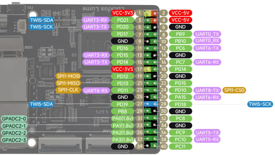
Configure PD18, physical pin 28 on the 40-pin header, as PWM2 channel 2 to output control pulses for an SG90 servo.
| Item | Configuration |
|---|---|
| Physical pin | Pin 28 on the 40-pin header |
| SoC pin | PD18 |
| Pin multiplexing function | pwm2_2 (Function 5) |
| Controller / channel | pwm2 / channel 2 |
2.2 Device Tree Configuration
-
Open the board-level device tree in the SDK:
device/config/chips/t153/configs/luckfox_lume/linux-5.10-origin/board.dts -
Set the multiplexing function of PD18 to pwm2_2:
&pio {lume_pwm2_2_pd18_active: lume-pwm2-2-pd18-active {pins = "PD18";function = "pwm2_2";drive-strength = <10>;bias-disable;};lume_pwm2_2_pd18_sleep: lume-pwm2-2-pd18-sleep {pins = "PD18";function = "gpio_in";bias-pull-down;};};&pwm2 {status = "okay";};&pwm2_2 {pinctrl-names = "active", "sleep";pinctrl-0 = <&lume_pwm2_2_pd18_active>;pinctrl-1 = <&lume_pwm2_2_pd18_sleep>;status = "okay";}; -
Compile the device tree and package the image:
./build.sh dts./build.sh./build.sh pack
2.3 Viewing PWM Devices
root@luckfox:~# ls -l /sys/class/pwm
total 0
lrwxrwxrwx    1 root    root     0 Sep  3 07:03 pwmchip0 -> ../../devices/platform/soc@3000000/20a0000.pwmcs0/pwm/pwmchip0
lrwxrwxrwx    1 root    root     0 Sep  3 07:03 pwmchip16 -> ../../devices/platform/soc@3000000/20c0000.pwm2/pwm/pwmchip16
lrwxrwxrwx    1 root    root     0 Sep  3 07:03 pwmchip8 -> ../../devices/platform/soc@3000000/20b0000.pwmcs1/pwm/pwmchip8
2.4 Exporting a PWM Channel
echo 2 > /sys/class/pwm/pwmchip16/export
ls /sys/class/pwm/pwmchip16/pwm2/
After a successful export, the following attributes are available:
capture duty_cycle enable period polarity power uevent
period: PWM period, in ns.duty_cycle: High-level duration, in ns; must not exceedperiod.polarity: Output polarity; can be set tonormalorinversed.enable: Write 1 to enable output or 0 to stop it.
2.5 Outputting a 50 Hz Signal with a 1.5 ms Positive Pulse Width
After exporting the channel for the first time, if enable, period, and duty_cycle are all 0, set a valid period before configuring the other attributes. This avoids an Invalid argument error caused by period=0:
cd /sys/class/pwm/pwmchip16/pwm2

echo 0 > enable
echo 0 > duty_cycle
echo 20000000 > period
echo normal > polarity
echo 1500000 > duty_cycle
echo 1 > enable
The period is 20,000,000 ns (20 ms), corresponding to 50 Hz. With normal polarity, the high-level duration is 1,500,000 ns (1.5 ms), corresponding to a 7.5% duty cycle for the SG90 center position.
Always ensure that duty_cycle <= period when configuring PWM. After testing, stop and release the channel:
echo 0 > /sys/class/pwm/pwmchip16/pwm2/enable
echo 2 > /sys/class/pwm/pwmchip16/unexport
Stopping PWM does not disconnect the servo's power supply. Turn off the external power supply after testing.
3. PWM Control (Python)
-
Example program: Use 1.5 ms as the center position and vary the pulse width sinusoidally between 1.1 and 1.9 ms to move the servo back and forth periodically.
#!/usr/bin/env python3import mathimport signalimport sysimport timefrom pathlib import PathPWM_CHIP = Path("/sys/class/pwm/pwmchip16")CHANNEL = 2PWM = PWM_CHIP / f"pwm{CHANNEL}"PERIOD_NS = 20_000_000CENTER_NS = 1_500_000RANGE_NS = 400_000STEPS = 200running = Truedef stop(signum, frame):global runningrunning = Falsedef write_value(path, value):with path.open("w") as file:file.write(str(value))def main():exported = Falseconfigured = Falseenabled = Falsefailed = Falsesignal.signal(signal.SIGINT, stop)signal.signal(signal.SIGTERM, stop)try:if not PWM.is_dir():write_value(PWM_CHIP / "export", CHANNEL)exported = Truetime.sleep(0.1)if int((PWM / "period").read_text()) > 0:write_value(PWM / "enable", 0)write_value(PWM / "duty_cycle", 0)write_value(PWM / "period", PERIOD_NS)configured = Truewrite_value(PWM / "polarity", "normal")write_value(PWM / "duty_cycle", CENTER_NS)if running:write_value(PWM / "enable", 1)enabled = Trueprint("PWM2: PD18 (pin 28), 50 Hz, pulse 1.1-1.9 ms",flush=True)print("Press Ctrl+C to return to center and stop.", flush=True)while running:for step in range(STEPS):if not running:breakphase = 2.0 * math.pi * step / STEPSpulse_ns = int(CENTER_NS + RANGE_NS * math.sin(phase))write_value(PWM / "duty_cycle", pulse_ns)time.sleep(0.02)except (OSError, ValueError) as error:print(f"PWM error: {error}", file=sys.stderr)failed = Truefinally:if enabled and not failed:try:write_value(PWM / "duty_cycle", CENTER_NS)time.sleep(0.3)except OSError as error:print(f"PWM center error: {error}", file=sys.stderr)failed = Truestopped = Trueif configured:try:write_value(PWM / "enable", 0)except OSError as error:print(f"PWM stop error: {error}", file=sys.stderr)failed = Truestopped = Falseif exported and stopped:try:write_value(PWM_CHIP / "unexport", CHANNEL)except OSError as error:print(f"PWM unexport error: {error}", file=sys.stderr)failed = Trueif not failed:print("PWM stopped.")return 1 if failed else 0if __name__ == "__main__":sys.exit(main()) -
Open the PWM device:
PWM_CHIP = Path("/sys/class/pwm/pwmchip16")CHANNEL = 2PWM = PWM_CHIP / f"pwm{CHANNEL}"Control channel 2 through sysfs. If the
pwm2directory does not exist, create it by writing toexport; otherwise, reuse it. -
Configure and output PWM:
if int((PWM / "period").read_text()) > 0:write_value(PWM / "enable", 0)write_value(PWM / "duty_cycle", 0)write_value(PWM / "period", PERIOD_NS)If the existing period is nonzero, disable output and clear the previous pulse width first. If the initial period is 0, set a valid period first to avoid
Invalid argument. Then selectnormalpolarity, set an initial pulse width of 1.5 ms, and enable output. -
Adjust the duty cycle:
phase = 2.0 * math.pi * step / STEPSpulse_ns = int(CENTER_NS + RANGE_NS * math.sin(phase))write_value(PWM / "duty_cycle", pulse_ns)time.sleep(0.02)The period is fixed at 20 ms (50 Hz). Pulse widths of 1.1 to 1.9 ms correspond to duty cycles of 5.5% to 9.5%. With 200 steps at approximately 20 ms per step, a full back-and-forth cycle takes about 4 seconds.
-
Run the program:
python3 PWM.pyOutput:

4. PWM Control (C)
-
Complete code: Output a 50 Hz control signal through PWM sysfs to move the servo smoothly back and forth along a sine wave.
#define _POSIX_C_SOURCE 200809L#include <errno.h>#include <math.h>#include <signal.h>#include <stdio.h>#include <time.h>#include <unistd.h>#ifndef PWM_CHIP#define PWM_CHIP "/sys/class/pwm/pwmchip16"#endif#define PWM_PATH PWM_CHIP "/pwm2"#define CHANNEL "2"#define PI 3.14159265358979323846#define PERIOD_NS 20000000U#define CENTER_NS 1500000U#define RANGE_NS 400000U#define STEPS 200static volatile sig_atomic_t running = 1;static void stop(int signum){(void)signum;running = 0;}static void delay_ns(long ns){struct timespec delay = { .tv_sec = 0, .tv_nsec = ns };while (nanosleep(&delay, &delay) < 0 && errno == EINTR) {}}static int write_value(const char *path, const char *value){FILE *file = fopen(path, "w");if (!file) {perror(path);return -1;}int failed = fprintf(file, "%s", value) < 0;if (fflush(file) == EOF)failed = 1;if (fclose(file) == EOF)failed = 1;if (failed)fprintf(stderr, "PWM write failed: %s\n", path);return failed ? -1 : 0;}static int write_number(const char *path, unsigned int value){char text[32];snprintf(text, sizeof(text), "%u", value);return write_value(path, text);}static int read_period(unsigned long long *period){FILE *file = fopen(PWM_PATH "/period", "r");if (!file) {perror(PWM_PATH "/period");return -1;}int failed = fscanf(file, "%llu", period) != 1;if (fclose(file) == EOF)failed = 1;if (failed)fprintf(stderr, "Cannot read PWM period\n");return failed ? -1 : 0;}int main(void){int exported = 0, configured = 0, enabled = 0, failed = 0;int stopped = 1;unsigned long long old_period;struct sigaction action = {0};action.sa_handler = stop;sigemptyset(&action.sa_mask);if (sigaction(SIGINT, &action, NULL) < 0 ||sigaction(SIGTERM, &action, NULL) < 0) {perror("sigaction");return 1;}if (access(PWM_PATH, F_OK) < 0) {if (write_value(PWM_CHIP "/export", CHANNEL) < 0)return 1;exported = 1;delay_ns(100000000L);}if (read_period(&old_period) < 0)goto error;if (old_period > 0) {if (write_value(PWM_PATH "/enable", "0") < 0 ||write_value(PWM_PATH "/duty_cycle", "0") < 0)goto error;}if (write_number(PWM_PATH "/period", PERIOD_NS) < 0)goto error;configured = 1;if (write_value(PWM_PATH "/polarity", "normal") < 0 ||write_number(PWM_PATH "/duty_cycle", CENTER_NS) < 0)goto error;if (running) {if (write_value(PWM_PATH "/enable", "1") < 0)goto error;enabled = 1;puts("PWM2: PD18 (pin 28), 50 Hz, pulse 1.1-1.9 ms");puts("Press Ctrl+C to return to center and stop.");fflush(stdout);}while (running) {for (int step = 0; step < STEPS && running; ++step) {double phase = 2.0 * PI * step / STEPS;unsigned int pulse_ns =(unsigned int)(CENTER_NS + RANGE_NS * sin(phase));if (write_number(PWM_PATH "/duty_cycle", pulse_ns) < 0)goto error;delay_ns(20000000L);}}goto cleanup;error:failed = 1;cleanup:if (enabled && !failed) {if (write_number(PWM_PATH "/duty_cycle", CENTER_NS) < 0)failed = 1;elsedelay_ns(300000000L);}if (configured && write_value(PWM_PATH "/enable", "0") < 0) {failed = 1;stopped = 0;}if (exported && stopped &&write_value(PWM_CHIP "/unexport", CHANNEL) < 0)failed = 1;if (!failed)puts("PWM stopped.");return failed ? 1 : 0;} -
Export the PWM channel:
if (access(PWM_PATH, F_OK) < 0) {if (write_value(PWM_CHIP "/export", CHANNEL) < 0)return 1;exported = 1;delay_ns(100000000L);}PWM_CHIPispwmchip16,CHANNELis"2", and the channel path ispwmchip16/pwm2. If export fails, the program exits immediately without configuring output. -
Set the period and duty cycle:
if (old_period > 0) {if (write_value(PWM_PATH "/enable", "0") < 0 ||write_value(PWM_PATH "/duty_cycle", "0") < 0)goto error;}if (write_number(PWM_PATH "/period", PERIOD_NS) < 0)goto error;Set a 20 ms period,
normalpolarity, and an initial pulse width of 1.5 ms. -
Control PWM output:
double phase = 2.0 * PI * step / STEPS;unsigned int pulse_ns =(unsigned int)(CENTER_NS + RANGE_NS * sin(phase));if (write_number(PWM_PATH "/duty_cycle", pulse_ns) < 0)goto error;delay_ns(20000000L);Update the pulse width sinusoidally between 1.1 and 1.9 ms, completing a back-and-forth cycle approximately every 4 seconds.
-
Unexport the PWM channel:
if (exported && stopped &&write_value(PWM_CHIP "/unexport", CHANNEL) < 0)failed = 1;Release the channel exported by the program only after output has stopped successfully.
-
Cross-compile using the ARM toolchain from the Lume SDK.
export PATH=<Luckfox_Lume_SDK>/out/toolchain/gcc-linaro-11.3.1-2022.06-x86_64_arm-linux-gnueabihf/bin:$PATHarm-linux-gnueabihf-gcc -std=c11 -O2 -Wall -Wextra PWM.c -o PWM -lm